

On the Basic Skills of Embedded Hardware Circuit Design
The electronic development path I took is actually the same as most people say. The basic route is analog electronics (proficient) → digital circuit design (master) → microcontroller (project development) → ARM hardware design (project development) → linux learning → linux Drive learning→ARM&linux bottom development (project development)→ARM&linux top development (project development)→project manager. I am still tossing on the road, and now I will share my lessons and experience with everyone, hoping to learn from novices.
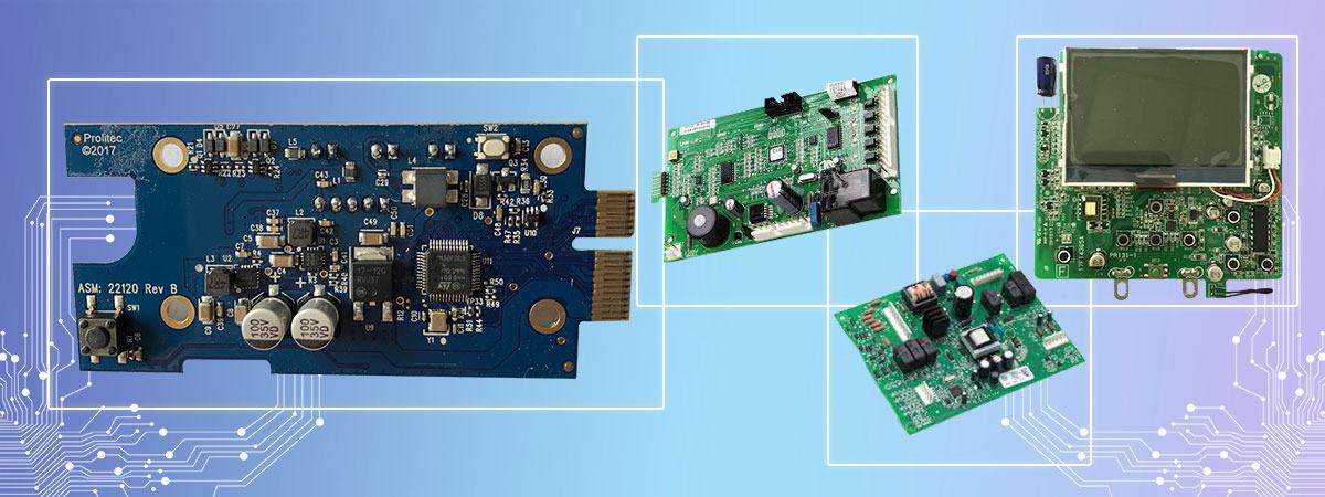
Embedded design is a huge project. Today, I will talk about several precautions in hardware circuit design. First of all, let's understand the embedded hardware architecture.
We know that the CPU is the soul of this system, and all peripheral configurations are related to it. This also highlights a feature of embedded design that hardware can be tailored. In the design of embedded hardware, the following points need to be paid attention to.
Embedded hardware circuit design
First, power supply is confirmed
The role of power in the embedded system can be regarded as the role of air on the human body, and even more important: the air that people breathe contains oxygen, carbon dioxide, and nitrogen, but the content is stable, which is equivalent to various clutter in the power system. We hope to obtain a pure and stable power supply that meets the requirements, but due to various factors, it is just our dream. This should focus on two aspects:
A, voltage
Embedded systems require power supplies of various magnitudes, such as the common 5v, 3.3v, 1.8v, etc. In order to minimize the power supply ripple, LDO devices are used in embedded systems. If DCDC is used, not only is it big, its ripple is also a headache.
B, current
The normal operation of the embedded system requires not only a stable and sufficient power supply, but also sufficient current (in fact, the power meets the requirements). Therefore, the load needs to be considered when selecting a power device. I generally leave a 30% margin when designing. .
If it is a multilayer board, the power supply part needs to be divided during layout. At this time, you need to pay attention to the division path and try to put a certain amount of power together. If it is a double-sided board, the width of the trace needs to be paid attention to, and the board should be as wide as possible. A suitable decoupling capacitor should be as close as possible to the power supply pin.
Embedded hardware circuit design
Second, crystal oscillator is determined
The crystal oscillator is equivalent to the heart of the embedded system, and its stability is directly related to its operating status and communication performance. Common oscillators include passive crystal oscillators and active crystal oscillators. First, determine its oscillation frequency, and secondly, determine the type of crystal oscillator.
A, passive crystal oscillator
The selection of matching capacitance and matching resistance is generally based on the reference manual. In the design of single-chip microcomputers, plug-in crystal oscillators are often used with ceramic capacitors. In ARM, in order to reduce space and facilitate wiring, four-corner passive crystal oscillators are often used with chip capacitors. Although we are familiar with the matching circuit of the fixed crystal oscillator, in order to be foolproof, we still need to see the reference manual to determine the size of the capacitor, whether it needs matching resistance and other details.
B, active crystal oscillator
has a better and more accurate clock signal, but in comparison, the price is higher than that of a crystal oscillator, so this is also a cost that needs to be paid attention to in the hardware circuit design.
When designing the circuit board, it is necessary to pay attention to the crystal oscillator trace as close to the chip as possible, and the key signal away from the clock trace. Add a grounding protection ring when conditions permit. If it is a multilayer board, it is also important to keep the key signal away from the trace of the crystal oscillator.
Third, reserve test IO ports
In the embedded debugging stage, when the pin resources are abundant, I usually reserve an IO port to connect to a led or speaker to pave the way for the next step of software writing. During the operation of the embedded system, the IO interface is appropriately controlled to determine whether the system is operating normally.
Embedded hardware circuit design
Fourth, external expansion storage equipment
If an embedded system has a power supply, crystal oscillator and CPU, then this is the smallest system we are familiar with. If the embedded system needs to run a larger operating system, not only does the CPU have an MMU, but the CPU also needs to be connected to SDRAM and NANDFLASH. If the cpu has SDRAM and NANDFLASH controllers, there is no need to consider the use of address lines too much in the hardware design. If there is no related controller, you need to pay attention to the use of address lines.
This part is an important point when LAYOUT, the reason is to make the relevant signal lines the same length to ensure that the signal delays are equal, and the clock and DQS differential signal lines are routed. Various wiring techniques need to be used comprehensively when wiring, such as symmetrical distribution with cpu, daisy chain wiring, T-type wiring, which all need to be selected based on the number of memories. Generally speaking, the more the number, the more complicated the wiring. , But knowing its key points, everything will be solved.
Fifth, functional interface
The most important thing for an embedded system is to control peripheral modules through various interfaces to achieve the purpose preset by the designer. Commonly used interfaces include serial ports (which can be used to connect modules such as Bluetooth, wifi and 3G), USB interfaces, network interfaces, JTAG interfaces, audio and video interfaces, HDMI interfaces, and so on. Since these interfaces are connected with external modules, it is an important task to do electromagnetic compatibility design. In addition, pay attention to the use of differential lines when LAYOUT.
Sixth, screen
This feature is listed separately because it is optional. If an embedded system is only used as a connector to connect to the peripheral device module, connected to the host computer through the relevant interface or directly connected to the network, then the screen is not needed. But if it is a consumer product that interacts frequently with users, you have to nag.
Capacitive screens are the first choice for embedded screens. In circuit design, attention should be paid to the layout of the touch screen connection line and the display connection line. In the process of routing, try to be as short as possible close to the main control cpu, and pay attention to the paired signal to go the differential line, and the RGB control signal to go the same length. The spacing of various signal traces follows the 3W rule to avoid mutual interference. In the design of the screen, it is necessary to ensure the power and prevent interference to prevent the occurrence of screen flickering and blurring.