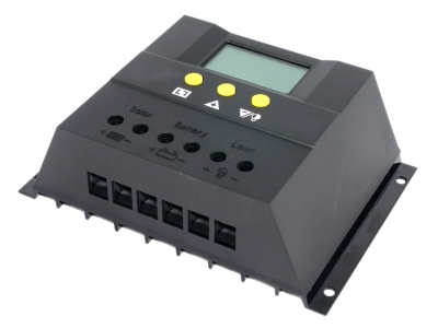
The full name of the solar controller is the solar charge and discharge controller. It is an automatic control device used in the solar power generation system to control the multi-channel solar cell array to charge the battery and the battery to supply power to the solar inverter load.
1. Direct charge protection point voltage: Direct charge is also called emergency charge, which belongs to fast charging. Generally, the battery is charged with high current and relatively high voltage when the battery voltage is low. However, there is a control point, also called protection The point is the value in the above table. When the battery terminal voltage is higher than these protection values during charging, the direct charging should be stopped. The voltage of the direct charge protection point is generally the "overcharge protection point" voltage, and the battery terminal voltage cannot be higher than this protection point during charging, otherwise it will cause overcharge and damage the battery.
2. Voltage at the equalization control point: After the direct charge is over, the battery will generally be left for a period of time by the charge and discharge controller to allow its voltage to drop naturally. When it drops to the "recovery voltage" value, it will enter the equalization state. Why design equalization? That is, after the direct charge is completed, there may be individual batteries "lag behind" (the terminal voltage is relatively low). In order to pull these individual molecules back and make all the battery terminal voltages uniform, it is necessary to match the high voltage with a moderate If the current is recharged for a short while, it can be seen that the so-called equal charge, which is "equal charge". The equalization time should not be too long, usually a few minutes to ten minutes, setting the time too long is harmful. For a small system equipped with one battery and two batteries, equal charging is of little significance. Therefore, the street light controller generally does not have equal charging, and only has two stages.
3. Floating charge control point voltage: Generally, after the equalization is completed, the battery is also left to stand for a period of time to make its terminal voltage drop naturally. When it drops to the "maintenance voltage" point, it enters the floating charge state, similar to "Trunk Current charging" (that is, low current charging), when the battery voltage is low, charge a little, and charge a little when the battery voltage is low, so that the battery temperature will not continue to rise. This is very good for the battery. , Because the internal temperature of the battery has a great influence on charging and discharging. In fact, the PWM method is mainly designed to stabilize the battery terminal voltage and reduce the battery charging current by adjusting the pulse width. This is a very scientific charging management system. Specifically, in the later stage of charging, when the remaining capacity (SOC) of the battery is> 80%, the charging current must be reduced to prevent excessive outgassing (oxygen, hydrogen and acid gas) due to overcharging.
4. Over-discharge protection termination voltage: This is easier to understand. The battery discharge cannot be lower than this value, which is the stipulation of the national standard. Although battery manufacturers also have their own protection parameters (enterprise standard or industry standard), they still have to move closer to the national standard. It should be noted that for safety reasons, the over-discharge protection point voltage of the 12V battery is generally added to 0.3v as temperature compensation or the zero-point drift correction of the control circuit, so that the over-discharge protection point voltage of the 12V battery is 11.10v, then The over-discharge protection point voltage of the 24V system is 22.20V.
Music TV speaker power amplifier board
Karaoke TV speaker amplifier board
2.4G TV speaker power amplifier board
Home theater speaker power amplifier board
High-end Bluetooth Speaker PCBA
High power bluetooth speaker PCBA
Portable small bluetooth speaker PCBA
Outdoor sports Bluetooth audio PCBA
Desktop Bluetooth Speaker PCBA
Wooden box bluetooth speaker PCBA
Teaching speaker power amplifier board
Smart home and other power amplifier boards
Karaoke microphone PCBA
DSP main control B6208 specifications
太阳能控制器全称为太阳能充放电控制器,是用于太阳能发电系统中,控制多路太阳能电池方阵对蓄电池充电以及蓄电池给太阳能逆变器负载供电的自动控制设备。
1、直充保护点电压:直充也叫急充,属于快速充电,一般都是在蓄电池电压较低的时候用大电流和相对高电压对蓄电池充电,但是,有个控制点,也叫保护点,就 是上表中的数值,当充电时蓄电池端电压高于这些保护值时,应停止直充。直充保护点电压一般也是“过充保护点”电压,充电时蓄电池端电压不能高于这个保护 点,否则会造成过充电,对蓄电池是有损害的。
2、均充控制点电压:直充结束后,蓄电池一般会被充放电控制器静置一段时间,让其电压自然下落,当下落到“恢复电压”值时,会进入均充状态。为什么要设计 均充?就是当直充完毕之后,可能会有个别电池“落后”(端电压相对偏低),为了将这些个别分子拉回来,使所有的电池端电压具有均匀一致性,所以就要以高电 压配以适中的电流再充那么一小会,可见所谓均充,也就是“均衡充电”。均充时间不宜过长,一般为几分钟~十几分钟,时间设定太长反而有害。对配备一块两块 蓄电池的小型系统而言,均充意义不大。所以,路灯控制器一般不设均充,只有两个阶段。
3、浮充控制点电压:一般是均充完毕后,蓄电池也被静置一段时间,使其端电压自然下落,当下落至“维护电压”点时,就进入浮充状态,类似于“涓流充电” (即小电流充电),电池电压一低就充上一点,一低就充上一点,一股一股地来,以免电池温度持续升高,这对蓄电池来说是很有好处的,因为电池内部温度对充放 电的影响很大。其实PWM方式主要是为了稳定蓄电池端电压而设计的,通过调节脉冲宽度来减小蓄电池充电电流。这是非常科学的充电管理制度。具体来说就是在 充电后期、蓄电池的剩余电容量(SOC)>80%时,就必须减小充电电流,以防止因过充电而过多释气(氧气、氢气和酸气)。
4、过放保护终止电压:这比较好理解。蓄电池放电不能低于这个值,这是国标的规定。蓄电池厂家虽然也有自己的保护参数(企标或行标),但最终还是要向国标 靠拢的。需要注意的是,为了安全起见,一般将12V电池过放保护点电压人为加上0.3v作为温度补偿或控制电路的零点漂移校正,这样12V电池的过放保护 点电压即为:11.10v,那么24V系统的过放保护点电压就为22.20V 。


